Understand the difference between scanned geometry, reference surfaces and editable parametric CAD before commissioning reverse engineering.
A 3D scan is a measurement source, not automatically a production model
STL and point-cloud data represent sampled surface geometry. This is useful for capturing complex shapes, checking fit or documenting existing equipment, but it usually lacks the design features, relationships and nominal dimensions needed for easy editing or manufacturing.
The right CAD conversion depends on your objective: visual reference, clearance checking, updated spare parts, design modification or manufacturing documentation.
Choose the intended output
- Reference geometry: a lightweight scanned model for context or packaging.
- Surface reconstruction: continuous surfaces to describe a complex outside shape.
- Parametric solid model: editable features, holes, fillets and patterns organised around design intent.
- Manufacturing package: a CAD model plus agreed dimensions, drawings, materials and tolerances.
Scan quality and missing features matter
Highly reflective, transparent or hidden regions can produce incomplete measurements. Scanning also captures wear, damage and manufacturing variation. An engineer must decide whether to reproduce these exactly or restore the intended nominal design.
For mechanical interfaces, physical measurements of holes, threads, bearing seats and mating surfaces may be required even when a scan looks visually accurate.
What to provide with your STL or point cloud
- The raw scan or cleaned mesh and the units or coordinate system.
- Photos of the original object and its use in the assembly.
- A list of critical mating interfaces and inspected dimensions.
- A statement of whether the part should be reproduced or redesigned.
- The desired CAD software, neutral file format and drawing deliverables.
Confirm accuracy with a fit or dimensional review
A well-rebuilt model should be checked against available measurements and, where appropriate, a mesh-to-CAD deviation review. Engineering judgement is still required to define nominal dimensions and acceptable tolerances; a small visual deviation does not always mean functional accuracy.
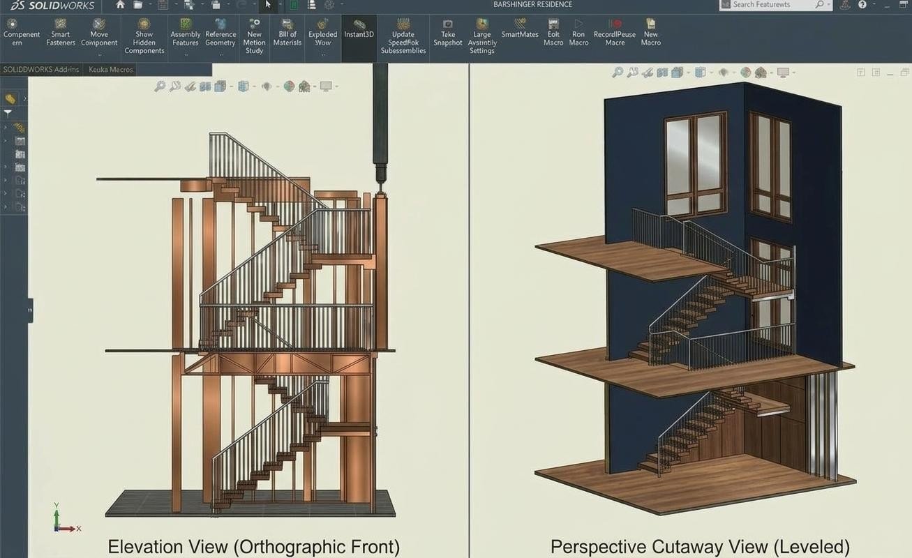
Our wooden staircase and railing project shows a scan-to-CAD style application. Explore reverse-engineering CAD services or share your files for a project discussion.