Dimensions alone are not enough. Check views, material, tolerances, BOMs, revisions and clear handover responsibilities.
Start with the intended manufacturing decision
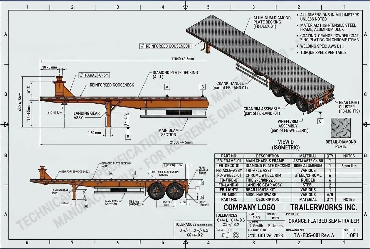
A manufacturing drawing package should tell a production team what is being made, how parts relate, and which requirements must be met. The level of detail depends on whether the receiver is a machine shop, steel fabricator, sheet-metal shop, assembler or external supplier.
Some dimensions belong on a part drawing; others are better described in an assembly drawing, installation drawing or BOM. Avoid relying on a 3D render alone for information that affects fit, inspection or procurement.
Core information to verify
- A clear part or assembly title, drawing number, revision and units.
- Correct material designation, finish, coating or treatment where applicable.
- Views, sections and details that make the geometry unambiguous.
- Dimensions and tolerances appropriate to function and inspection.
- Critical interfaces, hole positions, datums and assembly clearances.
- Standard parts and purchasing information in the BOM.
- Weld, bend, machining or installation notes where required.
Keep dimensions and tolerances purposeful
Dimensions should control the functional geometry without accidentally overconstraining the manufacturing process. Consider how the workshop will measure a feature and how tolerances stack up through mating components.
General tolerance notes are useful only when they are consistent with critical dimensions and the selected manufacturing process. Confirm the governing drawing standard and its edition with the customer or shop.
Part drawings versus assemblies
Part drawings explain individual components. Assembly drawings can show fit, orientation, hardware, identification balloons and the sequence or interfaces needed for assembly. Weldments may require both overall fabrication views and separate cut-part drawings.
For a large framework or trailer, member marking and an organised BOM are often as important as the 3D view. Clear filenames and references make it easier to find the right revision.
Practical pre-release checks
- Match drawing revision and CAD model revision.
- Check that detail views and parts list refer to the latest assembly.
- Confirm unit conventions, hole callouts and material specifications.
- Ask the fabrication team to review any special operations, tooling or tolerances.
- Assign approval responsibility for structural, safety-critical or code-controlled designs.
A consistent release package
A practical delivery might include source CAD, read-only PDFs, exchange files such as STEP, a BOM spreadsheet or PDF, and fabrication-specific DXF files. Include a brief release note identifying the approved revision, known open items and required checks.
See our flatbed trailer and steel fabrication projects, or review our drafting and technical documentation services.