How to hand over sheet-metal CAD so laser cutting, forming and welding teams know what to make.
A flat pattern is part of the handoff, not the whole handoff
A DXF file can drive a laser or waterjet cutting operation, but it does not by itself communicate bend direction, material grade, finish, grain direction or all assembly requirements. For a formed component, the manufacturing package should connect the flat blank back to the finished part.
The best handoff begins by confirming which operations your fabricator will perform, including cutting, bending, welding, riveting, fastening, coating or assembly.
Confirm inputs before generating the flat pattern
- Material grade and nominal thickness, not thickness alone.
- Inside bend radius, bend allowance method and shop tooling where available.
- Preferred bend sequence and accessibility for the press brake.
- Grain direction or surface finish where important.
- Hole-to-bend clearance, edge condition and formed feature requirements.
- Assembly interfaces and hardware installation access.
Do not assume a universal K-factor
Sheet-metal developed length depends on the manufacturing process, bend radius, thickness and the shop’s forming equipment. A CAD package may use a K-factor, bend allowance or bend deduction. None is universally correct for every machine and material combination.
Whenever practical, use the manufacturer’s proven bend table or a trial bend to calibrate the flat pattern. Validate the first article before relying on a new combination of material and tooling.
What to include with laser-cut DXFs
A clear 1:1 flat pattern should use consistent units and contain only the geometry the shop expects. Different machines and CAM workflows need different line layers or entity conventions, so align the export rules before delivery.
- Part number and matching drawing reference.
- Material grade, thickness and quantity.
- Bend lines or bend directions communicated using the agreed convention.
- No accidental duplicate or open contours in cutting geometry.
- Formed 3D view, finished dimensions and any relevant weldment detail.
Allow for real fabrication constraints
Check flange lengths, bend relief, tool clearance and interference in the formed state. Components that look correct as 3D geometry may still be difficult to fold or assemble. For stainless-steel equipment, also agree surface finish, cleanup and any hygiene-related requirements with the responsible fabricator.
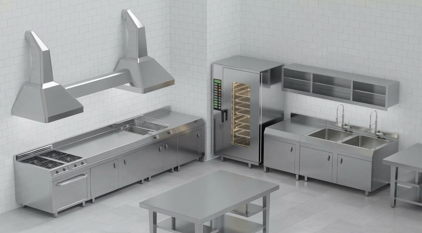
For a representative application, see the commercial kitchen sheet-metal project. Mechantra can prepare sheet-metal models, DXFs and fabrication drawings for review against your shop process.